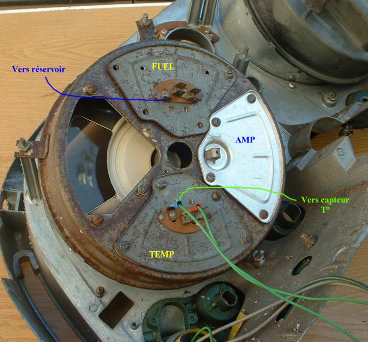
"speedo" adventures... |
- To disassemble, raise the small tabs (8) then raise the clear plastic with a fine screwdriver. Then remove " the outer rings " (paperboard and flat black metal ). Locate before disassembling the position of the tab of the clear face and the ring metal compared to the housing of the speedo !
- Remove at back " the lubrication wick " and 2 screws
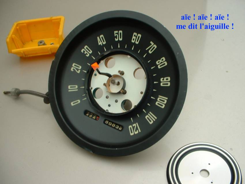
- With a fine screwdriver raise the front face of the speedo . Remove the rubber grommet of the trip mileage cable (or push it inside). Remove trip mileage knob (Allen wrench) and the chrome round nut (these parts are in the yellow box of the pic). Draw the speedo assl'y. from the housing , you obtain the pic below.

translation: raise the small tabs
-
Now you can remove the chrome center ornament from the plexi (clip) and clean the clear plastic. I used " stripe-eraser " for body paint and it is OK.
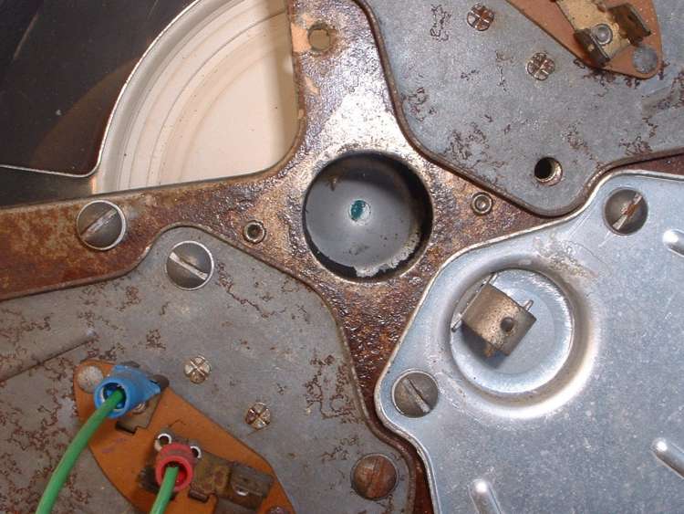
Arrive the delicate parts: you cannot reach the center if you
don't remove the needle. However it is inserted in a very fine axis (8/10 mm or
0.03 in.) which breaks very easily. I tried to draw moderately (I
already broke 2 of them!), it does not come. In despair of cause I used one
paint burner (in weak " position " nevertheless) and here is the result below
(photo 1) . At least I could withdraw the central hub cap! I reassure
you, the needle then could be rectified about... Notice the circular black band
between the 3 studs, it avoids with the light produced by the 2 top bulbs
of going towards the center. It is there that you "modify"
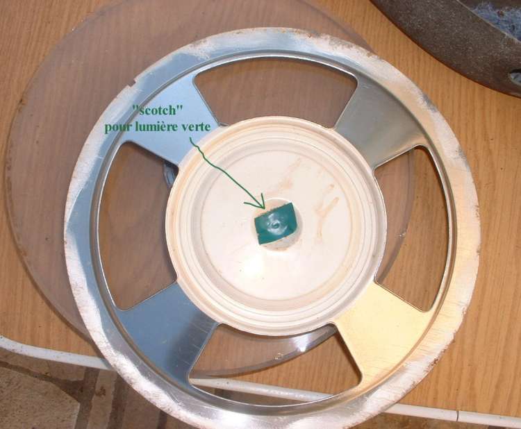
for the green " light "! You replace this opaque round by a green Scotch tape
passing around the studs (photo 3) . Thus the light will come towards
the center, will pass through the hole of the needle axis , and will be
green (see photo at the bottom of the page) after
reflection on the center "hubcap" inside white paint...
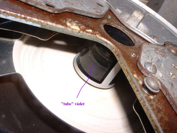
Attention with the " purple" ring, it is very fragile (glass). On some speedos
it is stuck but on other the glue has disappeared.
If you manage to withdraw the needle (photo 2) you will have access to " the head " of the speedo ( and set to 0 the odometer )
Writing on pics are translated below the thumbnails.
 |
 |
 |
| 1 (Ouch says the needle..) | 2 | 3 (green tape / purple ring) |
With the needle removed , you can remove
-
The central aluminium (hubcap) cover (3 small screws)
-
the central bracket which holds the "miles" wheels (photo 4).
-
The clip holding the axis of the trip odometer. Then, remove the unit (photo 5 then 6)
-
It is also necessary to remove the worm screw main shaft (also remove the almost identical horizontal shaft connected to the cable drive : check if the worm screw is in good condition. If cable stucks, the worm screw could be damaged. Lubricate !)
If you could not remove the needle, you can perform nevertheless items 3 and 4.
 |
 |
 |
| 4 (top: broken axle) / bottom: trip "wheels" bracket screw ) | 5 (green: remove bracket / yellow: remove clip) | 6 (bracket + worm screw axle + screw / clip / trip odometer assl'y) |
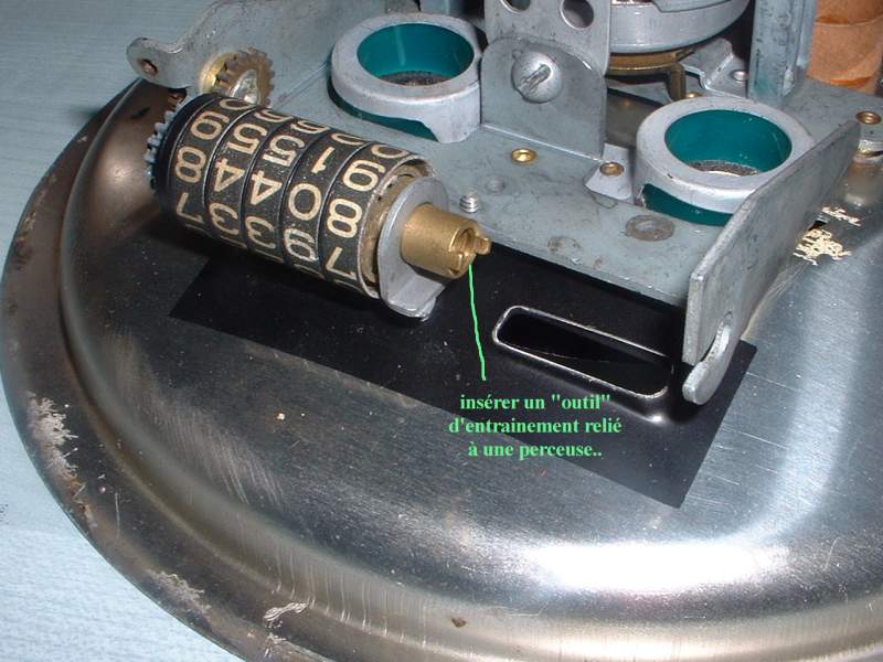
To set to 0, clear up with the "miles" wheels while not forgetting to check by re-installing the unit (attention with " the forks " of each wheel : need to be engaged !). If you could not have access to " the head ", insert a tool spining the wheels (photo 8 and 8 (a)) and good luck if the odometer must pass from 20000 to 0... About my speedo, I passed from 89800 to 3350 miles (which is the value registered on the speedo i've to replace) and it takes me around 1/2 hour.
 |
 |
 |
 |
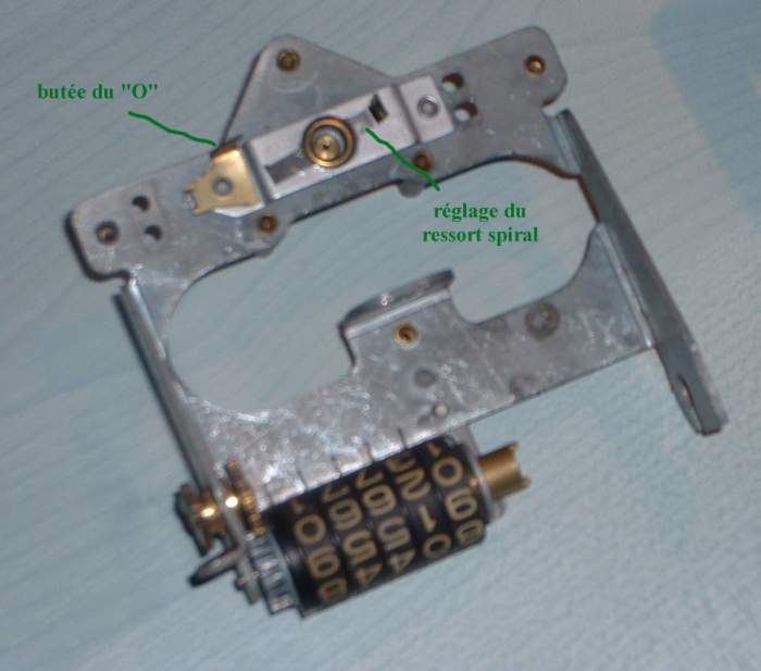
| 7 ( "0" stop / spiral spring adjust. brk) | 8 (slide a driving tool to set to 0) | 8 bis | 9
(at left , from top to
bt: rotating drum attached to needle / needle axis / spiral spring - at bottom: spiral spring adjust. / "0" adj. stop bkt - green: rotating drum housing attached to magnet and cable drive) |
Adjustments: Good luck !! From the moment when you disturbed the speedo (switches, axes, etc.) it is necessary to re-calibrate the speedo and it is better to do it before going up in the dashboard. It's the reason why i must remove mine !!
Calibration: equation
to be known: 1000 rpm (of cable ) = 60 mph.
Thus if you turn the drive axis to 1000 rpm, the needle
must indicate " 60 ". I do not have values for the km/h speedo, would be
necessary to test; but you should have 1000 rpm = 96 kmh since nothing changes
between the trans. and the speedo head . On kph speedo the only things which are
different are the printing of the numbers and number of teeth of the odometer
gears.
It remains you to find a drilling machine with rpm display. Values are
proportional thus if you turn to 800 rpm that will make 48 mph.
Not having a drilling machine with rpm display I used a chronometer watch : I put the trip meter at 0, I put a square end (connected by flexible device to a drilling machine with constant speed) in the speedo cable drive. An helper holds the chronometer and " SIGNAL ", one puts the drilling machine and the chronometer on the way (attention at the drilling machine speed ...). The number of revolutions is constant thus you read the speed, i.e 35 mph. You continue during 1 mile and you stop the chronometer(and the drilling machine.). Exemple: 1 mn 14 s (= 74 s) a rapid calculation: 1 : 74 x 3600 = 48,6 mph. Thus it will be necessary to adjust. You need several tests to confirm
It is exactly what it happened to me : first, check that the needle is well on 0, then it is necessary to adjust the 3 adjustments (photo 7, 9 and below) : 0 stop , the tension of the spiral spring and... the needle to be turned while holding the "turning drum". Attention, it is fragile, therefore if the speedo is right with a margin of 10 %, avoid touching there. If not, to slacken (or retighten) the spiral spring then put the needle on 0. Re-test etc...
If you are at this stage, the speedo is good... for the dustbin!!

translation: aimant tournant = "rotating" magnet / butée (tournante) du 0 = "0" adjusting stop bracket
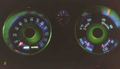
Note: real lighting is " less luminous " and the purple one is " deeper " ( " deep purple "....). Exposure time: 20 s.
And the other side?
much easier disassembling on the "gauges" side , except
the ammeter: indeed it functions by " induction ", emitted by the wire
where the intensity passes through: however to use this proprety the wire goes
through a closed loop which is connected to the apparatus, therefore it is
necessary to disconnect this wire (from " the ignition switch ") to withdraw
from the loop.
Once on the bench, the principle of disassembling of the front part is similar
to that of the speedo: raise the 8 small pins, remove the plexi, remove
the cross hub cap-mask unit . One discovers " the chimney " of lighting, made in
purple glass (or plastic) " The top" of the chimney has a hole where you
will put a adhesive green tape or glue a plastic green (you can also stick it on the mask,
photograph 14). This hole is originally used to evacuate heat (assumption
perso..), indeed there is, in the center, a 15W bulb .
Replace by lower bulb (10 W) while drilling in bulb socket 3 or 4 small
holes to evacuate heat.
It should be noted that on the photographs, oil pressure gauge is missing and that the needles had been repainted for " a future " use...

lumière verte (violette) = green (purple) light
 |
 |
 |
 |
| 10 | 11 | 12 | 13 (pink tube) |
 |
 |
||
| 14 (green adh. tape ) | back of speedo |